How to size a cable to IEC 60364: a worked example with derating and voltage drop
Work out the design current Ib and choose the next standard breaker In. Divide In by the product of the ambient, grouping and soil correction factors to get the rating the cable needs. Pick the smallest size with that rating, check the voltage drop, keep the larger of the two sizes, and confirm Ib ≤ In ≤ Iz.
IEC 60364-5-52 sets out how to choose a low-voltage wiring system, including its current-carrying capacity and voltage drop. The method is the same whether you work in Europe, the Middle East or Asia: find the current, protect it, derate the cable for where it runs, then check the voltage drop. This guide walks one 3-phase feeder through every step, using the same method and data as our IEC Cable Sizing + Voltage Drop Calculator.
A note on where the numbers come from
We do not reproduce IEC tables here. IEC 60364-5-52 gives current-carrying capacities, and correction factors for ambient temperature, grouping and soil, in its own tables; buy the standard or use your national wiring rules for those values.
The ratings and factors in this example come from the Data sheet of our calculator. The calculator works them out with the IEC 60287 thermal method (a heat balance of the cable and its surroundings, with safe-side margins), using generic cable dimensions. They are not copied from any standard's table, and national tables such as BS 7671 or AS/NZS 3008 will give somewhat different values. Each value below says which section of the Data sheet it comes from.
Step 1: design current Ib
For a load given in kW:
- 3-phase: Ib = P × 1000 ÷ (√3 × U × cos φ), with U the line-to-line voltage
- 1-phase: Ib = P × 1000 ÷ (U × cos φ)
If you already know the current (from a motor nameplate, for example), use it directly.
Step 2: protective device In
Choose the next standard breaker rating at or above Ib. IEC 60364-4-43 (protection against overcurrent) sets the coordination rule between the load, the device and the cable: Ib ≤ In ≤ Iz, where Iz is the cable's corrected current-carrying capacity. Because the cable must carry whatever the breaker lets through, the rest of the sizing works from In, not Ib.
Fuses need extra care. The calculator has an "extra derating factor" input for this, and its notes give 0.906 as an example for gG fuses.
Step 3: current-carrying capacity with correction factors
Installation method
IEC 60364-5-52 describes reference installation methods with letter codes. Our calculator uses A1, A2, B1, B2, C, D1, D2, E and F, for example method E is a multi-core cable in free air or on a perforated tray, and D2 is a cable laid directly in the ground. The method, the conductor (copper or aluminium), the insulation (PVC or XLPE) and the number of loaded conductors select one row of ratings.
Ambient temperature factor Ca
The ratings assume 30 °C air (20 °C ground). At a different temperature the calculator uses:
Ca = √((Tmax − Tamb) ÷ (Tmax − Tref)), rounded down to 0.01
Tmax is 70 °C for PVC and 90 °C for XLPE. Conductor losses grow with the square of the current, so the allowed current scales with the square root of the temperature rise you have left. (Data sheet, section 2.)
Grouping factor Cg
Cables next to each other heat each other. The grouping factor depends on the arrangement (bunched, single layer on a wall, perforated tray, ladder, buried) and on the number of circuits. (Data sheet, section 3.)
Soil factor Cs
For buried cables (D1, D2) a soil thermal resistivity other than the 2.5 K·m/W reference changes the rating. (Data sheet, section 4.) For cables in air, Cs = 1.
Required rating
Divide the breaker rating by all the factors:
It = In ÷ (Ca × Cg × Cs × extra factor)
Pick the smallest size whose table rating is at least It. Its corrected capacity is Iz = table rating × Ca × Cg × Cs.
Step 4: voltage-drop check
IEC 60364-5-52 has a clause on voltage drop in consumers' installations. The calculator uses:
ΔU = b × (R′ ÷ S × cos φ + X × sin φ) × Ib × L ÷ 1000
with b = √3 for 3-phase and 2 for 1-phase, L the one-way length in metres, S the size in mm², R′ the conductor resistivity at its maximum temperature (Ω·mm²/km) and X the reactance (Ω/km). Divide ΔU by U for the percentage. The voltage-drop size is the smallest size that stays within your limit; the calculator's default limit is 5 %.
Step 5: final size
The final size is the largest of three: the size for current, the size for voltage drop, and the minimum size (1.5 mm² copper, 16 mm² aluminium by default). Then confirm Ib ≤ In ≤ Iz and that the voltage drop is within the limit.
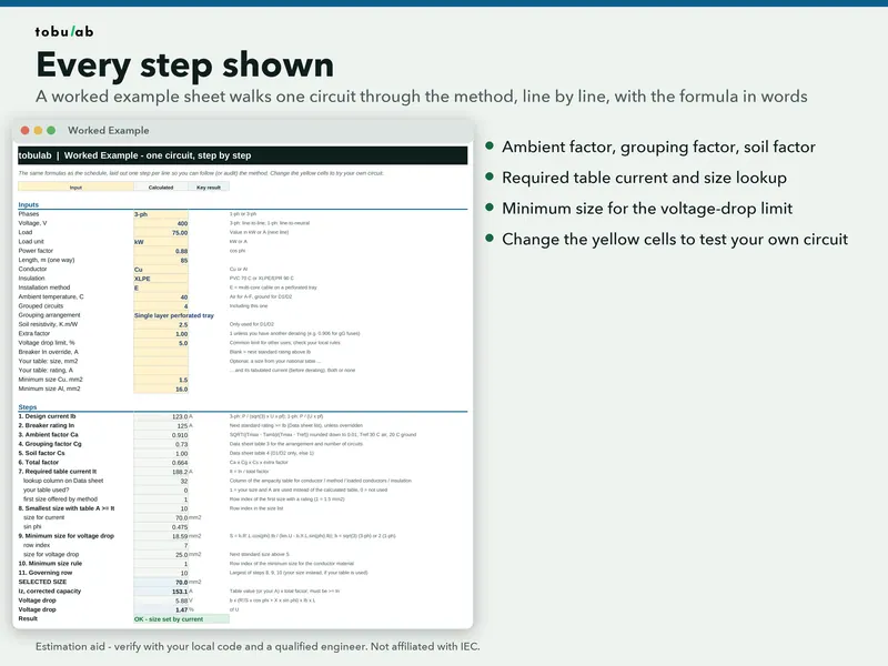
Worked example: a 75 kW feeder on a perforated tray
A 3-phase, 400 V, 75 kW load with power factor 0.88, fed by an 85 m copper XLPE multi-core cable on a single-layer perforated tray (method E), shared with 3 other circuits (4 in total), in 40 °C ambient. This is the example that ships in the calculator's Worked Example sheet. Every number below is printed by scripts/examples/cable-sizing-iec-60364-worked-example.py.
Steps 1 to 3
| Step | Calculation | Result | Value from |
|---|---|---|---|
| Design current Ib | 75 × 1000 / (√3 × 400 × 0.88) | 123.01 A | formula |
| Breaker In | next standard rating | 125 A | Data sheet, section 6 (breaker list) |
| Ambient factor Ca | √((90 − 40) / (90 − 30)) = 0.9129, rounded down | 0.91 | formula, Data sheet section 2 |
| Grouping factor Cg | 4 circuits, single layer perforated tray | 0.73 | Data sheet, section 3 |
| Soil factor Cs | not buried | 1.00 | — |
| Total factor | 0.91 × 0.73 × 1.00 × 1.00 | 0.6643 | — |
| Required rating It | 125 / 0.6643 | 188.17 A | — |
Choosing the size for current
Ratings: Data sheet, section 1, row Cu, method E, 3 loaded conductors, XLPE, 30 °C air.
| Size | Table rating | Meets It of 188.17 A? | Iz in this installation |
|---|---|---|---|
| 25 mm² | 120.5 A | no | 80.05 A |
| 35 mm² | 149.0 A | no | 98.98 A |
| 50 mm² | 186.5 A | no | 123.89 A |
| 70 mm² | 230.5 A | yes | 153.12 A |
| 95 mm² | 279.0 A | yes | 185.34 A |
50 mm² misses by a small margin, so current sets the size at 70 mm².
Voltage drop and final check
Constants: Data sheet, section 5: R′ = 22.42 Ω·mm²/km (copper at 90 °C) and X = 0.09 Ω/km (50 Hz).
| Check | Result |
|---|---|
| 50 mm² at 85 m | 7.92 V = 1.98 % |
| 70 mm² at 85 m | 5.88 V = 1.47 % |
| Smallest size within 5 % | 25 mm² |
| Final size = max(70, 25, 1.5) | 70 mm² |
| Iz = 230.5 × 0.6643 | 153.12 A |
| Ib 123.01 ≤ In 125 ≤ Iz 153.12 | OK |
| Voltage drop at 70 mm² | 1.47 % (limit 5 %) |
Result: 70 mm² copper XLPE, set by current-carrying capacity, on a 125 A breaker.
What changes on a long run
Move the same load to 320 m and voltage drop takes over:
| Size at 320 m | Voltage drop |
|---|---|
| 70 mm² | 5.53 % |
| 95 mm² | 4.27 % |
Final size = max(70, 95) = 95 mm², set by voltage drop, with Iz = 185.34 A. The current check still passes; the larger size is needed only to keep the voltage at the load.
Common mistakes
- Sizing from Ib instead of In. The cable can end up smaller than the breaker protecting it.
- Using the 30 °C rating in a hot plant room or roof space. In this example the 40 °C ambient alone multiplies every rating by 0.91.
- Forgetting the other cables on the tray. Grouping cost more than ambient here: 0.73 against 0.91.
- Using the single-phase factor for a 3-phase drop, or the reverse. b is √3 for 3-phase and 2 for 1-phase.
- Stopping after current and voltage drop. Short-circuit (adiabatic) withstand, earth-fault loop impedance, harmonics and parallel cables are separate checks. Our calculator does not cover them.
Using your own national table
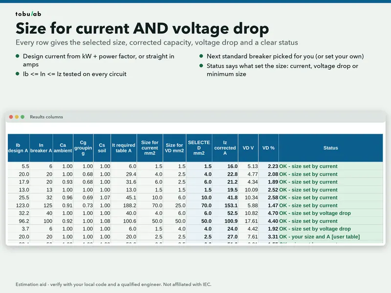
If your wiring rules give a different rating for the size you chose, the calculator lets you type that size and rating into the "Your table" columns of any circuit row; that row then uses your value and is flagged as "user table". The rest of the method stays the same.
Disclaimer: Estimation aid. Check against your local code and equipment datasheets.
Questions
- Why size the cable from the breaker rating In and not from Ib?
The breaker protects the cable, so the cable must carry whatever the breaker lets through. Sizing from In makes Iz at least In, so Ib ≤ In ≤ Iz holds.
- Do I multiply or divide by the correction factors?
Either, if you are consistent. Dividing In by the factors gives the table rating you need; multiplying a table rating by the factors gives Iz. Both lead to the same cable.
- What voltage-drop limit should I use?
It depends on your national rules and the type of supply. Our calculator's default is 5 %, and its notes give 3 to 5 % for final circuits and up to 8 % on private supplies as common limits.
- Is cable sizing finished once current and voltage drop pass?
No. Short-circuit (adiabatic) withstand, earth-fault loop impedance and harmonic derating are separate checks, and our calculator does not cover them.
Sources
- IEC 60364-5-52:2009, Low-voltage electrical installations, Part 5-52: Selection and erection of electrical equipment, Wiring systems (IEC Webstore)
- IEC 60364-4-43:2023, Low-voltage electrical installations, Part 4-43: Protection for safety, Protection against overcurrent (IEC Webstore)
- IEC 60287-1-1:2023, Electric cables, Calculation of the current rating, Part 1-1 (IEC Webstore)
Updated 2026-10-26 · by tobulab